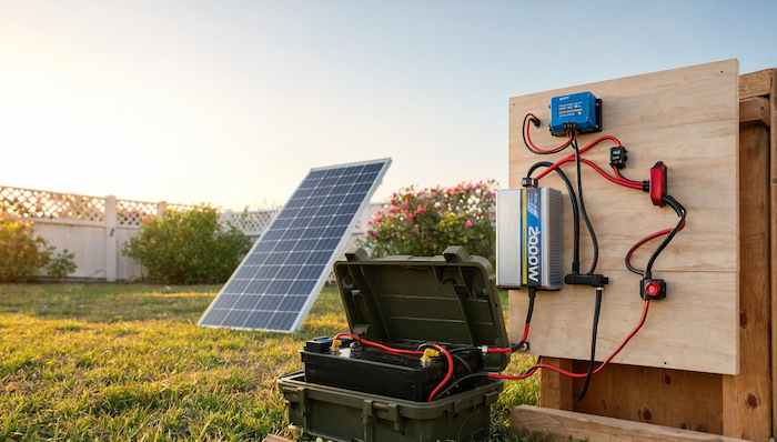
I love solar setup projects. This one hooked me instantly. I decided to build a 12-volt system with a 2,000-watt inverter and a 12-volt fuse block. It’s a popular setup. Plenty of people use it. I wanted to understand it inside and out before I touched a single wire. I split my process into two parts. First, I sat down and studied the theory. Then I built the thing. I think that order matters. You need to understand why before you start connecting parts.
Understanding the Basics
I started with the big picture. Solar panels collect sunlight. They send that energy to a charge controller. The charge controller regulates the flow and sends it to batteries. The batteries store it. When I need power, I flip on the inverter. It converts stored battery energy into usable AC power for my devices: phones, laptops, and even a fridge. Simple concept. Powerful system.
The One Formula That Runs the Whole Show
I had to learn one formula before anything else made sense: Watts ÷ Volts = Amps.
My inverter runs at 2,000 watts. My whole system runs at 12 volts. So I divided 2,000 by 12. I got 166.67 amps. That number determines everything: my wire size, my fuse size, and my switch rating. I like to compare this to something familiar. A typical wall outlet in an American home runs at 120 volts and 15 amps. Multiply those together and you get 1,800 watts. That’s roughly what my 2,000-watt inverter puts out. No wonder this setup is so popular. It mimics what we already plug into every day.
Accounting for Inverter Inefficiency

Here’s something I didn’t expect. No inverter runs at 100% efficiency. Mine sits around 85-90%. I had to adjust my formula: 2,000 ÷ 12 ÷ 0.85 = 196 amps. That’s the real number I needed to design around.
Choosing the Right Wire
I checked an amperage chart to find my wire gauge. My system needed to handle 196 amps. That number fell between the 150 and 200 amp brackets on the chart. I always round up in situations like this. Undersized wire can overheat. It can even start a fire. I chose 2/0 gauge wire. It comfortably handles 200 amps over the short distance from my batteries to my inverter. I used this same method: check the amp draw, check the chart, and round up—for every other connection in my build.
Cable Lugs, Fuses, Switches, and Bus Bars
I needed a few more components to tie everything together:
Cable lugs connect my wires to the posts on my inverter, fuse block, battery, and switches. I matched lug size to wire gauge and post diameter.
Fuses protect my wiring. I sized each fuse to match the maximum amperage its wire could safely carry, then placed them close to the power source.
Switches let me disconnect power instantly. I installed one between my solar panels and charge controller and another between my batteries and the rest of the system.
Bus bars act as a central hub. I ran a red one for positive connections and a black one for negative. Every major component ties into these.
I also added an optional shunt connected to a battery monitor. It’s not required, but I like tracking my battery status in real time.
Building the Layout
I laid everything out on a sheet of plywood. Your space might look completely different—a van, an RV, a shed, or a boat. It doesn’t matter. The principles stay the same. I usually recommend sketching a diagram first. However, I did things backward this time. I built the full system first, then created my diagram afterward. Seeing the finished layout helped me understand exactly what I needed to draw.
Wiring the Inverter to the Batteries
I tackled the thickest cables first. They don’t bend easily, so I wanted them locked into position early.
Here’s the path I built:
Positive side: inverter → fuse → positive bus bar → switch → battery
Negative side: inverter → negative bus bar → shunt → battery
I cut my 2/0 gauge wire with a bolt cutter. Then stripped the insulation carefully, then hammered on cable lugs using a heavy-duty crimping tool. I kept both lugs on each cable at matching angles—otherwise, nothing lines up when you try to mount it.
I added shrink wrap over every connection point. Red for positive. Black for negative. I only had black cable available at the hardware store, so I wrapped some of it in red tape to keep my polarity clear. I connected a 200-amp fuse near the inverter, then ran the wire to my positive bus bar. From there, I connected a 275-amp switch—well above my 200-amp maximum draw—before running the final cable toward the battery.
Adding Solar Through the Charge Controller
My charge controller handles up to 520 watts on a 12-volt system. I connected four 100-watt monocrystalline panels in series. I calculated my fuse size using the panels’ short-circuit current rating (5.21 amps) multiplied by a standard industry factor of 1.56. That gave me 8.13 amps. I rounded up and installed a 10-amp inline fuse. I also added a DC-rated circuit breaker between my panels and charge controller. This lets me cut solar input whenever I need to. From the charge controller, I ran 8-gauge wire—sized for the controller’s 40-amp rating—down to my positive and negative bus bars, protected by a 40-amp fuse near the controller itself.
Installing the 12-Volt Fuse Block
My fuse block can handle up to 125 amps. The chart called for 1-gauge wire at that rating. But I only planned to run one or two small 12-volt devices, pulling less than an amp combined. So I intentionally downsized to 4-gauge wire, rated for 100 amps, and added a 5-amp fuse inside the block itself. I even skipped the recommended fuse between the busbar and fuse block, since my load was so light. That’s a call you should make based on your own usage—not mine.
Connecting the Batteries
I used two 12-volt, 100-amp-hour lithium iron phosphate batteries, wired in parallel. Before connecting them, I checked that both batteries showed matching voltage. They did, so I moved forward. I activated both batteries from shelf mode using the manufacturer’s included tool, holding the button until the indicator light turned blue. After that, I connected them with a Cat5 cable so I could monitor them together, then linked the shunt to track real-time status through my battery monitor. I made sure my main switch was off before connecting anything, and I placed a 200-amp fuse right at the battery terminal: the true origin point of my system’s power.
Grounding and Final Testing
I grounded both my inverter and charge controller using six-gauge green wire, connected to a grounding rod outside my shed. If you’re building this in a vehicle, ground to the chassis instead. Once everything was connected, I ran a full test. I checked the inverter’s sine wave output. I plugged in a few devices and monitored my battery levels. Afterwards I checked my cables and lugs for heat; everything stayed cool. That told me my wire sizing was correct.
Sketching the Final Diagram
After confirming everything worked, I built my diagram. I started with the inverter as my anchor point and worked outward from there: batteries, bus bars, fuses, and switches. Red lines marked positive connections. Black lines marked negative. I added grounding last.
I labeled everything with simple shorthand: W for wiring, F for fuse, and S for switch. Nothing fancy. Just a system that made sense to me.
My Biggest Takeaway
This project isn’t as complicated as it looks. It really comes down to three things: use the right wire gauge, use the right fuse size, and use the right cable lug for every connection. Get those right, and the rest falls into place. If you’re planning your own build, sketch your diagram before you buy a single part. It’ll save you time, money, and a few headaches along the way. Stay safe out there.
About the Author